1. Background
For many years following the first spacecraft launches by the original space faring nations, spacecraft size and complexity increased as more and more functionality was driven into each satellite and robotic explorer. We assume that this early trend was fueled at least partly by the fact that larger and larger launch vehicles could be constructed and launched to orbit and nations were willing and able to build these rockets. The budgets and political environments of this era allowed, and possibly even encouraged this trend.
Today however, we are witnessing a counter-trend with regards to spacecraft size. Resources required to develop and then lift large spacecraft on exceedingly costly launch vehicles are becoming increasingly constrained. But perhaps even more important, large spacecraft are no longer the only platforms available to execute scientific, technological, or defense missions. Partly driven by the ever-increasing capabilities of the shrinking integrated circuit and related technologies, small spacecraft can now be seriously considered to perform many of the missions that were traditionally the sole domain of large spacecraft. Further, novel space architectures are being considered using small spacecraft that were not even feasible using monolithic space platforms.
The ongoing evolution of small and very small spacecraft, typified by the university-developed Cubesat platform, is leading the charge for the transformation of the space technology and the aerospace industries. Cubesats, and small spacecraft platforms that can be accommodated on launch vehicles possessing excess launch performance margin as a secondary payload, embody a number of attractive features, the biggest of which is low development cost. Similarly, the creation of adapters and mechanisms such as the Poly Picosat Orbital Deployer (P-POD) for the deployment of Cubesats, and other devices such as the motorized Light Band from Planetary Systems Corporation, have facilitated the integration complexity and launch related aspects for small satellites and are making their accommodations relatively routine. However, as more and more small and very small spacecraft are being utilized by military and civil space, as well as educational institutions, there is a growing need for a low-cost, yet flexible method to operate these small spacecraft, potentially simultaneously as a constellation. Since the same cost constraints and pressures are at work, and expensive operations solution coupled with a low-cost development and launch capability does not make sense. Therefore, we need to apply the same innovative forces and techniques to the ground segment portion of the architecture that we have successfully implemented for the space segment. We anticipate that these innovative forces will take the form of novel development tools and environments, automation and smart systems and flight software, flexible ground networks and equipment, and universally accepted standards and approaches in order to enable low cost, widely accessible ground operations capabilities that are consistent with and build upon the momentum and value of the small spacecraft revolution.
The Hawaii Space Flight Laboratory (HSFL) of the University of Hawaii at Manoa is currently developing a comprehensive open set of software tools with supporting hardware that is designed to primarily support the operations of one or more small spacecraft, but can also perform an important role in the design, development, and testing phases of spacecraft missions. This set of mission operations tools operate within the architecture named COSMOS (Comprehensive Open-architecture Space Mission Operations System). COSMOS is being developed by HSFL in collaboration with NASA Ames Research Center (ARC) under a three-year NASA EPSCoR grant beginning in September, 2010. COSMOS will be particularly suited for small organizations with a very limited development and operations budget, such as universities. However, it is not just restricted to universities or educational activities. The COSMOS tools will initially be installed in two mission operation centers (MOCs) at HSFL and NASA ARC, and used in support of several small satellites from both organizations. Spacecraft design and construction and subsequent mission support are all dependent on a number of unique protocols and technologies generally not found in Commercial-Off-The-Shelf (COTS) software. At the same time, although there is some significant overlap between the needs of all these activities, similar technologies are often used in markedly different ways, making tools incompatible at different phases, and leading to duplication of effort. As a result, tools for spacecraft design and mission support suffer from a number of flaws from the point of view of small missions developers. First among these is cost. While commercial packages capable of performing the COSMOS functions are available, they come at a high buy-in and maintenance costs. A second common flaw of many existing tools is that they are of limited scope. Often, two different tools that perform greatly similar functions will be required at different phases of the process. This serves not only to exacerbate the cost problem, but also leads to problems with integration, and with training. Finally, some areas, especially in mission support, are covered only by proprietary solutions, or not at all.
Although many universities operate their own small satellites, the operations systems are usually patched together using available general COTS applications, such as MATLAB®, LabView®, and MS Excel®, and are designed to be only sufficient to meet their immediate needs. COSMOS provides a solution that is being optimized from the beginning for mission operations and to add new and different types of satellites with minimum effort.
Other systems similar to COSMOS exist, such as ESA’s European Ground Operation System (EGOS)/Spacecraft Control Operation System (SCOS); JPL’s Advanced Multi-Mission Operations System (AMMOS); and GSFC’s General Mission Analysis Tool (GMAT). However, each of these has a problem for use with small satellite (university class) missions, such as restricted use, or unavailability of source code with requirement to have the system customized by provider. ESA’s Global Educational Network for Satellite Operations (GENSO) is a university class network currently being developed by several universities, but has some usage and operations limitations that are being addressed by COSMOS.
2. Architecture and Design
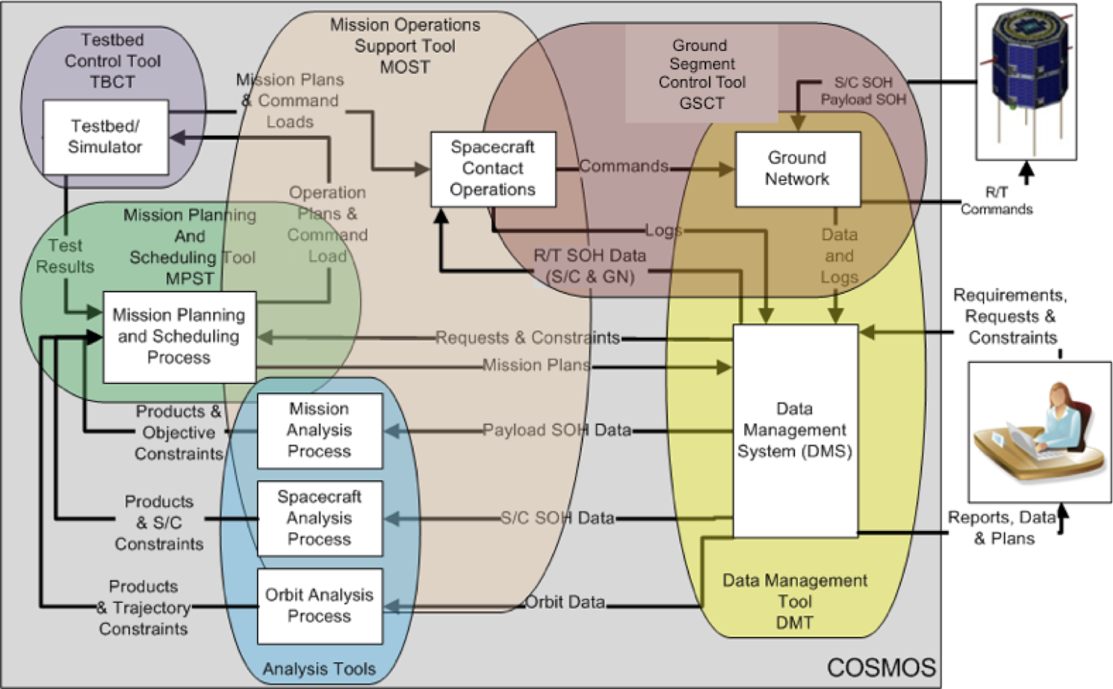
The central pieces of this architecture are the visualization tools, support tools, and underlying programs that produce and manipulate the data needed by the rest of the tool sets. It combines both the software and unique hardware needed to support mission operations, including an operations test bed (OTB) and simulators. The simulators are all software applications, and the OTB combines simulators with spacecraft hardware where possible to mimic as closely as possible the reaction of the spacecraft to commands and operational states.
The basic philosophy behind the construction of this architecture is that its elements (tools and other programs) will be easy to port to a new location and to modify for operating with new satellites. This is enabled by being an “open architecture.” This approach means not only that the source code of its major elements and structure are available, but also that it is designed to accept external modules (which may not have source code available) as plug-ins through standard, well-defined interfaces in order to increase the overall capability of COSMOS for the desired application. However, it is recognized that there could be ITAR issues with COSMOS since it is designed to help control satellites. Therefore, we use a more limited definition of “open architecture” than the common one of having the source code in the public domain. We intend to provide COSMOS to only those entities (US government agencies, companies, or universities) which are allowable within ITAR restrictions. However, for those entities, the COSMOS source code will be available. Hopefully, in the future this restriction can be relaxed as ITAR restrictions are redefined or COSMOS obtains an ITAR clearance from the government.
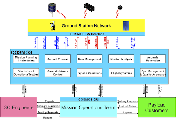
A computer can be provided at each mission ground station to provide the interface between COSMOS and the ground station for data management (both to and from the ground station), and to monitor and possibly control the operations of the ground station. The various tools of COSMOS provide the graphical interface between the MOT and the COSMOS functions. The MOT communicates with spacecraft engineers to assist in state-of-health (SOH) matters, such as anomaly resolution, and reports of the condition of the spacecraft and receives in return any constraints or tasking that may be required. The MOT also communicates with the various payload customers to receive reports on the status of the instruments and mission accomplishment goals, as well as to receive payload tasking requests. COSMOS will have websites or other means to allow the spacecraft engineers and customers to monitor the status of the mission directly without having to go through the MOT.
- Mission Planning and Analysis which also includes command sequencing and the simulators and operations testbed (OTB);
- Contact Operations which includes pre-contact operations, real-time contact operations, and post-contact operations both in the MOC and the ground network;
- Data Management which includes transfer of all data throughout COSMOS and between COSMOS external locations; data processing, such as engineering units conversion and Level 0 data processing; and data archiving;
- Mission Analysis which includes support by the MOT to analyze and trend spacecraft and ground network state-of-health (SOH) data, orbital and trajectory data, and mission accomplishment data to help determine the mission success Measures of Effectiveness (MOEs). The results of the Mission Analysis process are fed back to the mission planners, spacecraft engineers (especially for resolving spacecraft anomalies), mission management, and customers.
The figure also shows the primary tools that COSMOS provides for interfacing with the MOT to control these operations processes. The rest of COSMOS provides the underlying processes and engines that move, generate, and process the data used by COSMOS and the MOT. Each of the major software tools and programs that make up COSMOS will be described in the following sections along with our approach to developing them. The various tools, major agents/engines, and other software of the COSMOS system are shown in the following figure.
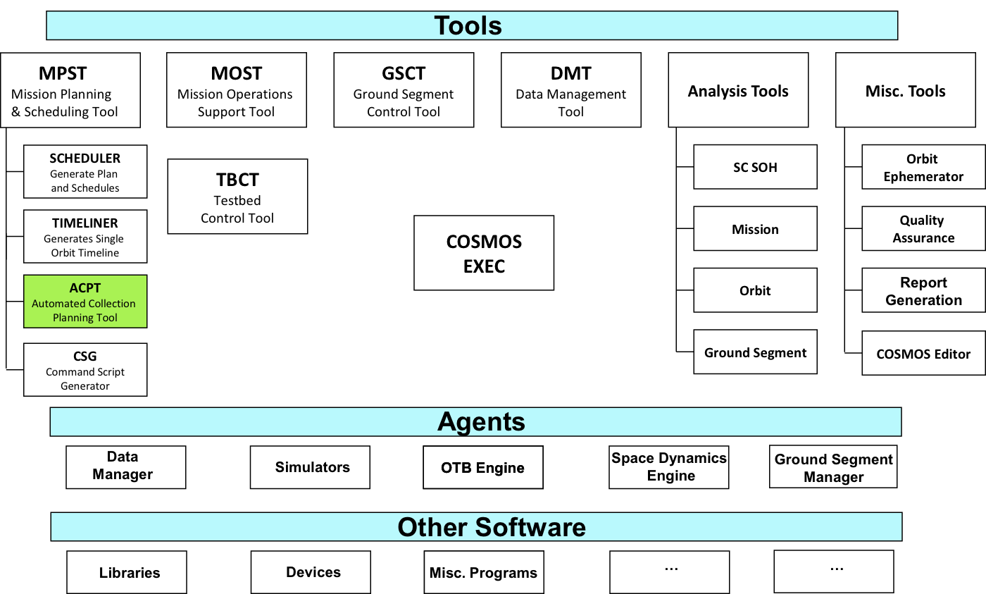
3. Tools
The tools of COSMOS include software applications that human operators interact with to control COSMOS and the mission operations processes. Each of the tools are described below.
3.1 Mission Operations Support Tool (MOST)
3.2 COSMOS Executive Operator (CEO)
3.3 Mission Planning and Scheduling Tool (MPST)
3.3.1 Scheduler
3.4 Automated Collection Planning Tool (ACPT)
3.5 Timeliner and Command Script Generator
3.6 Ground Segment Control Tool
3.7 Data Management Tool
4. Software Design
The overall goal of the COSMOS software design is to create a unified set of software elements that fulfills the following roles:
- Provide the functionality required for the design and operation of the majority of small satellites
- Provide this functionality in a uniform manner across the life cycle of satellite design, development and operation
- Make the functionality readily accessible through the use of commonly available protocols and standards, and an open software approach.
- Support existing satellite software either through direct incorporation, or the creation of translating interfaces.
To achieve the above goals, the COSMOS development team has both adopted, and defined a set of rules to govern the development process. The purpose of these rules is to constrain development along relatively straightforward pathways, while retaining the flexibility needed to achieve the desired goals. For the purposes of this section, these rules will be divided into the three broad categories of Type, Function, and Protocols and Standards. Type will describe the various levels of software development that will be provided within COSMOS. Function will describe the functionality addressed by each software element. Finally, Protocols and Standards will list the protocols and standards we plan to embrace as necessary to COSMOS.
4.1 Type
The COSMOS software should be roughly envisioned as four levels of software, progressing from the rudimentary to the most complex. At the most basic level is the Foundation layer. This consists of a large number of support routines upon which the higher layers can be built. These routines provide the basic functionality as detailed below. The next two layers, Programs and Agents, are roughly parallel. Both build on the Foundation layer to provide more advanced functionality. The main difference is that Programs are one-shot deals that perform their function and exit, while Agents are persistent, communicating with the rest of the world to receive their orders. The fourth layer is Tools. Tools will incorporate both Foundation layer functions, the launching of Programs, and communications with Agents to perform complex functions in direct interaction with humans.
4.2 Function
The COSMOS software will have to provide a large amount of functionality, some of which is not yet fully defined. However, the COSMOS development team has initially identified certain key areas of function that will be absolutely necessary. Those already identified are listed below:
- Higher level mathematics, especially in the area of vector and matrix manipulation. Along with this is the need to define data types that work with these functions.
- Conversions between different coordinate systems, for both position and attitude. These also require their own specific data types.
- Conversion between different time systems.
- Orbital calculations.
- Simulations, including orbital and attitude propagation, thermal, power, etc.
- Protocol support
- Agent support
4.3 Protocols and Standards
COSMOS is first and foremost a Unix-based package. In respect of this, and the desire to have as much control over the software as possible, the Foundation layer and all Programs and Agents will be written in POSIX compliant C. In order to support the various upper level elements that will require C++, all code will be compiled against the GNU G++ compiler. This will not preclude the introduction of libraries written in FORTRAN, where unavoidable. In addition, support for Java will be investigated in later phases.
Although Unix will be the primary Operating System platform, we desire to support other platforms as well. In particular, modifications will be made, where necessary, to allow the Foundation code to compile and operate on the latest version of Windows 7 and MacOS 10. Programs and Agents will be supported in these operating systems where possible. Tools are created in the Nokia QT GUI environment and therefore have the potential of running on any environment supported by QT.
Communications are through standard RS-232, USB and Ethernet. More specifically, a SLIP protocol with a 16bit CRC appended to each packet is used for any Serial interactions. Standard IP protocols are used for all Ethernet interactions; only UDP based protocols are used for Earth/Space communications. Specific protocols will be adopted as appropriate. Protocols that have already been identified include:
- JSON (JavaScript Object Notation): a simple text based method to be used for storage of all information and data. (web site: http://www.json.org/)
- NORM (NACK Oriented Reliable Multicast): a UDP based file and message transfer protocol that is robust, and can even function over a simplex connection. This will be used for Earth/Space communications. (web site: http://cs.itd.nrl.navy.mil/work/norm/)
- LCM (Lightweight Communications and Marshalling): a UDP Multicast protocol for signaling and transferring data blocks between processes. This is the primary means of inter process, and inter processor communication within a local network. (web site: http://code.google.com/p/lcm/)
5. Operations Test
The COSMOS Operations Test-Bed (OTB) uses an open-source system architecture that integrates hardware and software components and tools to operate a low cost Satellite System Simulator (e.g. FlatSat) which can be integrated into the MOC setup for command scripting testing, personnel training, mission rehearsals and anomaly resolution. The OTB has tools for satellite technology integration and development that allows for cheaper satellite subsystem integration and testing. The OTB tools are based on COTS that are affordable to university labs while some tools are being developed under the COSMOS project using proven standards and made available to the small sat community. The OTB is part of the four major processes in mission operations that are supported by COSMOS, namely the Mission Planning and Scheduling, Real-time contact operations, mission analysis, and anomaly resolution.
The OTB will be initially used within the Hawaii Space Flight Laboratory smallsat development program and after a successful implementation and usage it is expected to be installed in other facilities, like other universities, within the COSMOS project umbrella.
One important aspect of the OTB is that it makes possible to provide an interface with different satellite hardware and simulators that are needed to make the global testing procedure for different missions. This platform also allows the mission segment functional simulation and mission rehearsals from the command sequence to the software and hardware performance. To completely operate the OTB its setup must integrate six main constituents: (1) The actual Mission Operations Center (MOC) control tool, or MOST; (2) the Ground Station Simulator (GSS); (3) the Satellite System and Subsystem Simulator (SSS); (4) the Test Bed engine (TBE); (5) The test bed controller tool (TBCT); and (6) the Test bed controller user interface. This segmentation is expressed in Figure 5.
The MOC System Simulator allows the end user to conduct the near real-time spacecraft system and subsystems testing and operational activities, including mission planning; assessment and maintenance; instrument health monitoring; and communications, command and control function. The integral part of the MOC System Simulator is MOST, which is one of the two interface tools between the OTB and the end user.
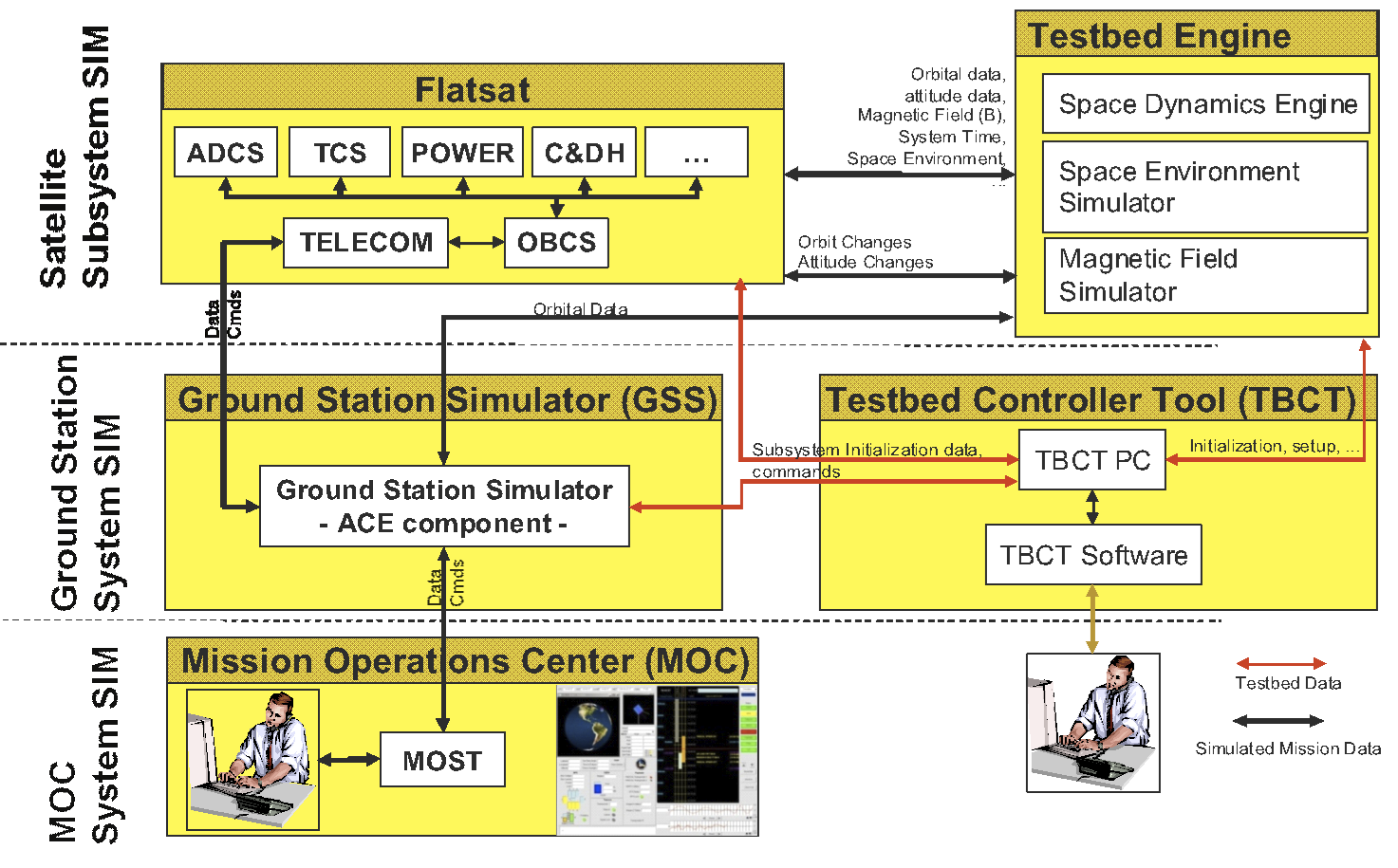
The Test Bed Dynamics Engine provides a software simulated space environment to the OTB to allow a more realistic operation of the whole platform. It has a Space Dynamics Engine for orbital data generation and a Space Environment Simulator that integrates different physical models like the atmospheric models, the magnetic field model and others. The dynamical engine also controls the different hardware and software configurations in the satellite system simulator and allows the tuning and mixing of signals and interrupts, adding noise and possible failure modes. All this is done either controlled by the controller user interface or a scripting sequence.
The Test Bed Control Tool (TBCT) is an application to support the experimental setup for the OTB architecture. The TBCT interfaces with the GSS, the satellite system, the Test Bed Engine and the end user. It allows initializing and controlling the satellite system platform and the Test Bed Engine according to the user decisions or scripting.
The user interface control tool is software like MOST to operate and change the OTB parameters and testing sequences.
The COSMOS OTB can incorporate different hardware parts that are made available for testing and experimentation. These components can include common sensors, actuators and other hardware systems that are common for satellite integration. Table 1 has an overview of these components.
Table 1: OTB Hardware Components
| Hardware Type | Components |
|---|---|
| Sensors | IMUs, Magnetometers, Accelerometers, Gyros, Sun Sensors, Star Sensors, Horizon Sensors, Thermal Sensors, GPS, Cameras |
| Actuators | Magnetic Torquers, Reaction Wheels, Momentum Wheels, Thrusters, Motors for reaction systems, Control Momentum Gyros |
| Test tools | Air Bearing Platform, Sun Simulator, Thermal Vacuum Chamber, Testing Software |
| Support Tools | Hardware development platforms, Micro Controllers development boards |
| Other Systems | Battery Systems, Telecom Systems, Motor controllers, Electronic components, Helmholtz Chamber, Sun Panels, PC 104 boards, Solar Panels, |
Finally, the OTB is designed to have the following operation features:
- Calibration and testing of hardware components
- Integrate Software tools for hardware simulation
- Subsystem validation & monitoring
- Subsystems interaction & dynamics monitoring
- Pseudo-environment input (available up to a certain degree)
- Anomaly resolution support
- Measurable performance: like pointing, timing, speed, fast, power, etc.
- Remote control of the OTB using scripts
- Near real time testing and simulations
- Mission Training and rehearsals
- Trending and analysis
- System operation rehearsals and simulations with statistical analysis (e.g. Monte Carlo)
- Operability with different standard software development tools and languages: MATLAB, LabView, Python, C/C++, and/or other engineering COTS software utility tools.
- Support the development and operational test for different satellites One important aspect to note is that the OTB is being designed so that it may be remotely operated, allowing people from different remote locations use this same setup to help in their satellite development or mission operations.